
[BROT] Optical Transfer Raman V2.0
Our NEW Optical Transfer Raman technology takes it to the next level.
With easy optimization for multiple laser excitation wavelengths, ultra-fine filter adjustments from the outside, and a design that’s easy to handle and transport, it’s perfect for synchrotron beamlines.
A multidisciplinary development
The development of the second version of the BETSA® Raman Optical Transfer (BROT) involved a multidisciplinary approach to optimize optics, electronics, and mechanics, ensuring a high-performance and reliable system.
The design process addressed various constraints and material requirements to guarantee measurement accuracy and performance. See detailed list of key elements and constraints considered for optimizing version V02.
Precise optical alignment is required to maximize Raman signal collection and minimize losses, while minimizing optical and electrical noise sources. The system must remain stable over time for repeatable and accurate measurements.
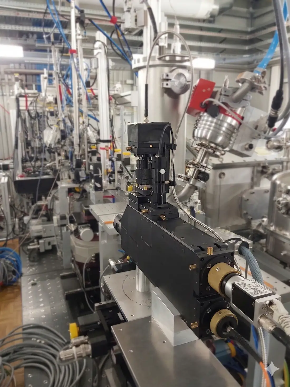
Key elements and constraints
Hover a card to reveal the details.
Type of laser: «Adaptable» diode laser or solid-state laser, fibered or not, with a selectable wavelength of 491 nm, 532 nm or 660 nm. Three configurations — the filter set matches the laser you choose, one at a time.
Laser power: Must be sufficient to excite molecular vibrations without damaging the sample. Typically between 10 mW and 500 mW.
Stability and spectral purity: Good wavelength stability and a narrow linewidth are crucial.
Objective: Use high-quality microscopic objectives (10x, 20x) to focus the laser beam on the sample in most DACs and environments.
Collimators: To maintain a well-aligned and focused beam.
Notch or edge filters: To block the laser light and allow the passage of the scattered Raman light.
Low-frequency cut-off: Set by the dichroic — 175 cm−1 at 532 nm; signal from ≈ 180, fully efficient at 340. Stokes only.
This part is not covered by BETSA®; we only provide the BROT, which will adapt to the client’s choice of spectrometer and detector.
Spectrometer: With sufficient resolution to distinguish Raman bands. Should include an adjustable entrance slit and a high-quality diffraction grating.
Detector: Cooled CCD to reduce thermal noise and increase sensitivity. EMCCD detectors can be used for applications requiring high sensitivity.
Sample holders: Stable and adaptable for different types of samples (solids, liquids, gases).
Microscope: To align and observe the sample, often integrated with the Raman optical head for increased precision. At least 4 XY stages (precision <5µm) for aligning the camera, optical fiber output, light input for internal illumination, and the incoming laser beam coupled with a tilt mechanism.
Control: Software for laser control, interfacing, and operation.
Data acquisition: Manufacturer’s software for the spectrometer for data collection and spectral analysis.
Synchronization electronics: To coordinate the operation of the laser, spectrometer, and detector.
Cooling: Cooling systems for sensitive electronic components.
Safety enclosure: To protect the user from laser radiation.
Vibration isolation: To reduce mechanical noise.
Reference standards: Materials with well-known Raman spectra to validate the device’s performance.
Mechanical adjustments
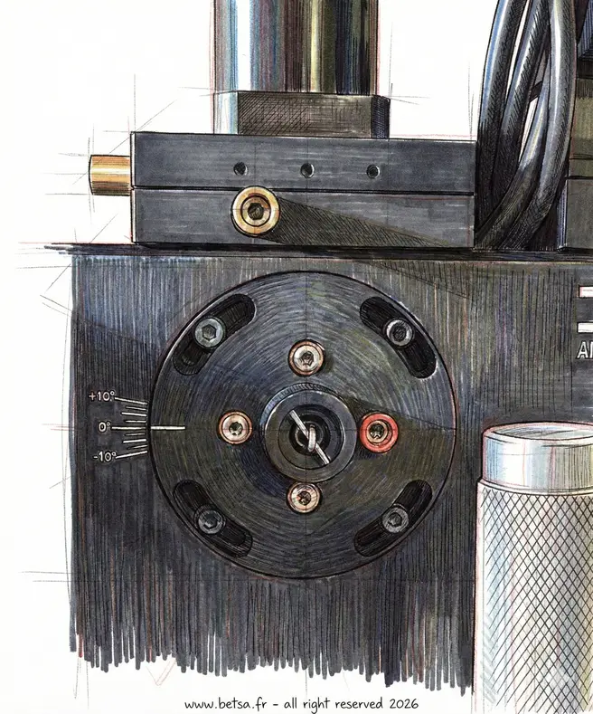
Filter alignment tilt
This adjustment system is designed as a block that can be adjusted in tilt for perfect alignment thanks to micrometric screws and return springs.
It is also removable from the outside allowing filters to be exchanged corresponding to laser wavelengths.
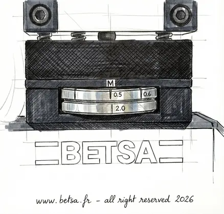
Laser tilt and filter wheel
This assembly is a combination of the tilt of the laser adjustment with micrometer screws mounted on a filter wheel for laser attenuation.
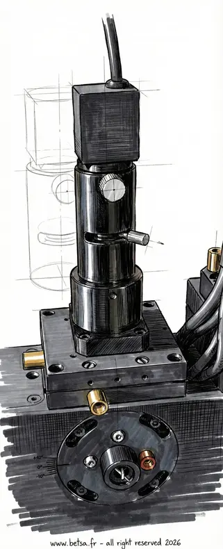
Lighting input
Lighting input, mounted on an XY table for adjustment of internal lighting reflecting light from the inside, directly onto the sample surface in the DAC.
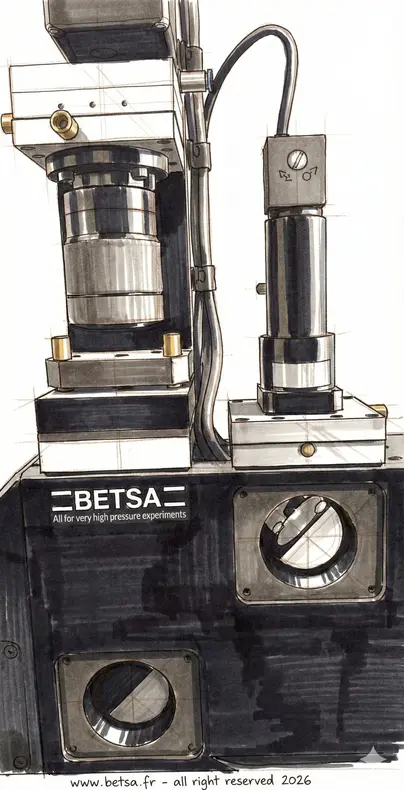
Beam expander alignment
Adjustments and alignment of the laser with an XY stage in the beam expander with tilt.
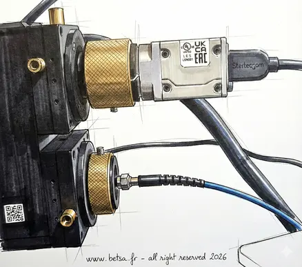
XYZ adjustment for camera and fiber
XY and Z adjustment of the camera visualization input for optimal focusing and images as well as collection on the optical fiber towards the Raman spectrometer.
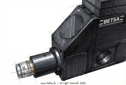
Return mirror adjustment
Adjustment of the return mirror from the outside thanks to a tilt.
BROT 2.25 electronic control unit
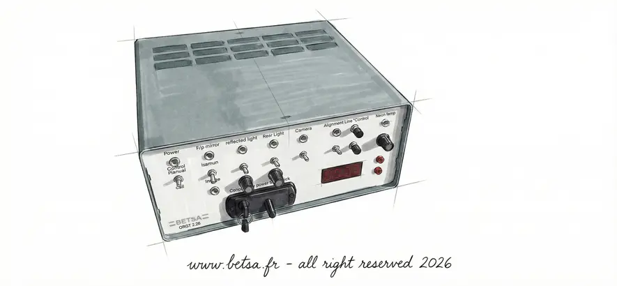
General presentation
The BROT 2.25 electronic control unit serves as the command center for the entire optical system. It centralizes power supply and management for all subsystems, including the laser, shutter, lighting, and camera. Designed for flexibility, it offers dual control modes: a manual interface for direct operation and a USB connection for full software automation.
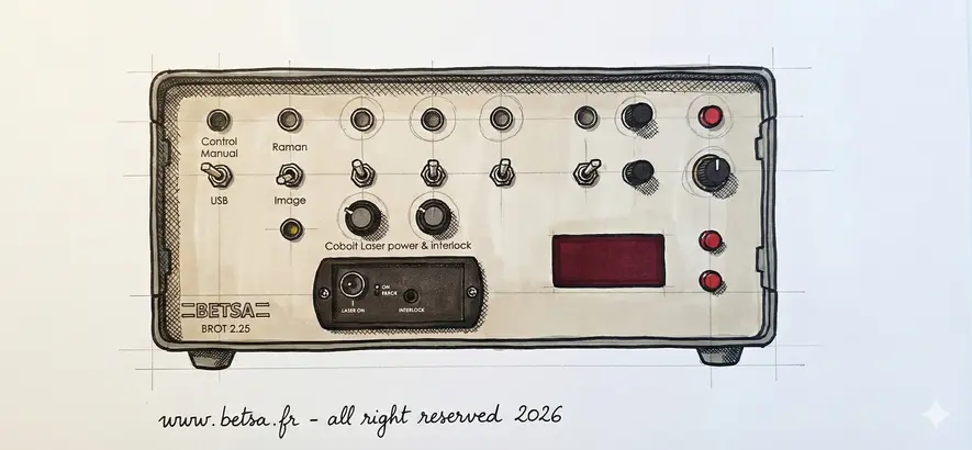
Front panel
The front panel provides immediate physical control over the experiment. It features a master key switch and interlock connector to ensure laser safety class 3B compliance. Users can manually toggle the motorized shutter between Raman and Imaging modes, adjust LED intensities via rotary potentiometers, and precisely regulate the alignment laser voltage using digital controls.
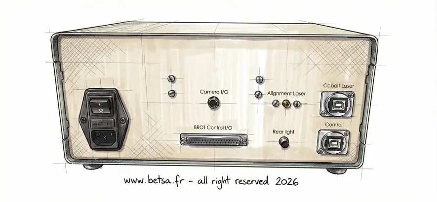
Rear panel
The rear panel concentrates all essential connectivity. It houses the main power switch and fuse, alongside dedicated ports for the camera and the optical head control (Sub-D). It includes an SMA output for the alignment laser, a jack for external backlighting, and dual USB ports to interface the laser and the system with the computer.
New option
Motorized filter wheel
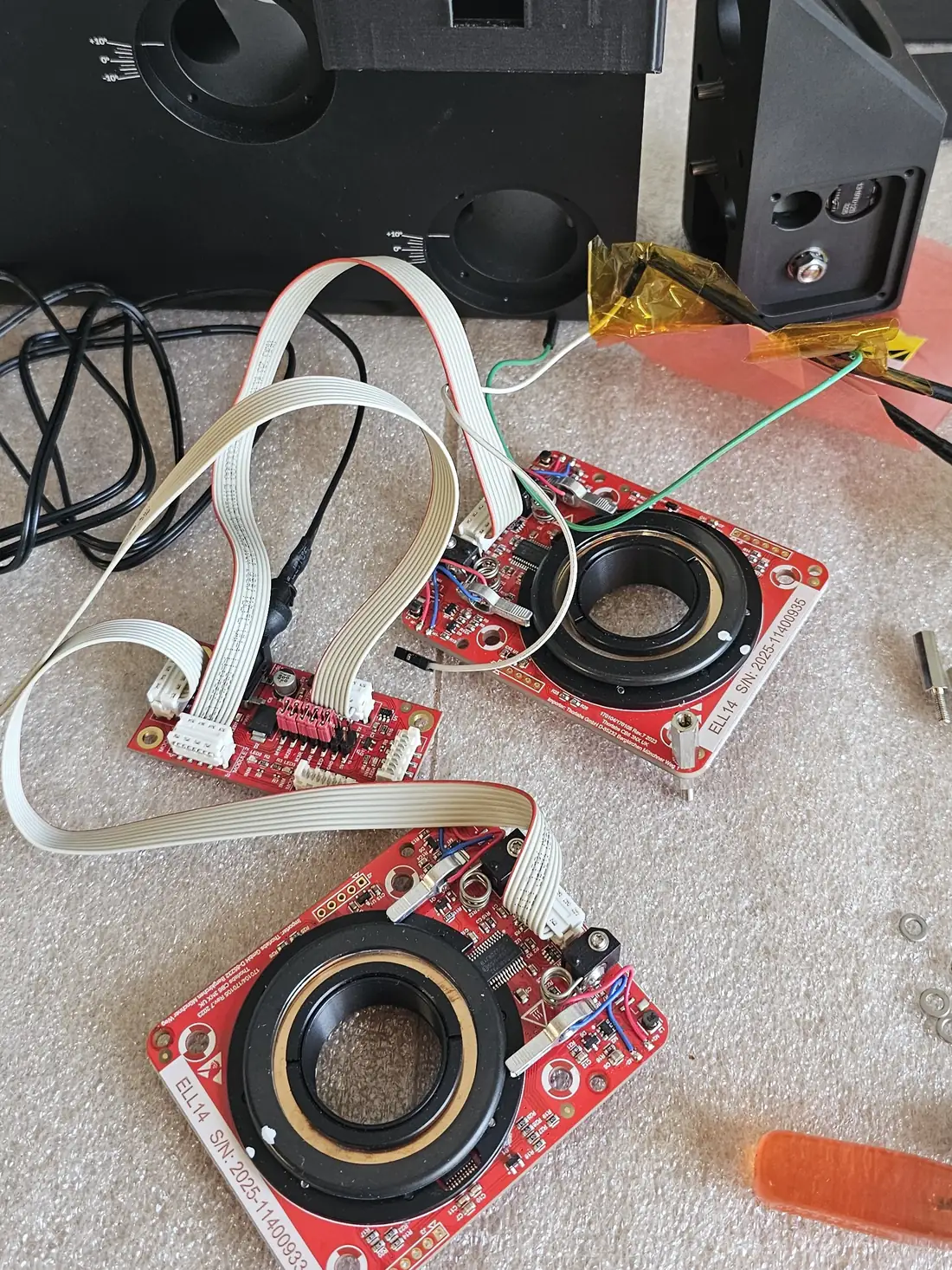
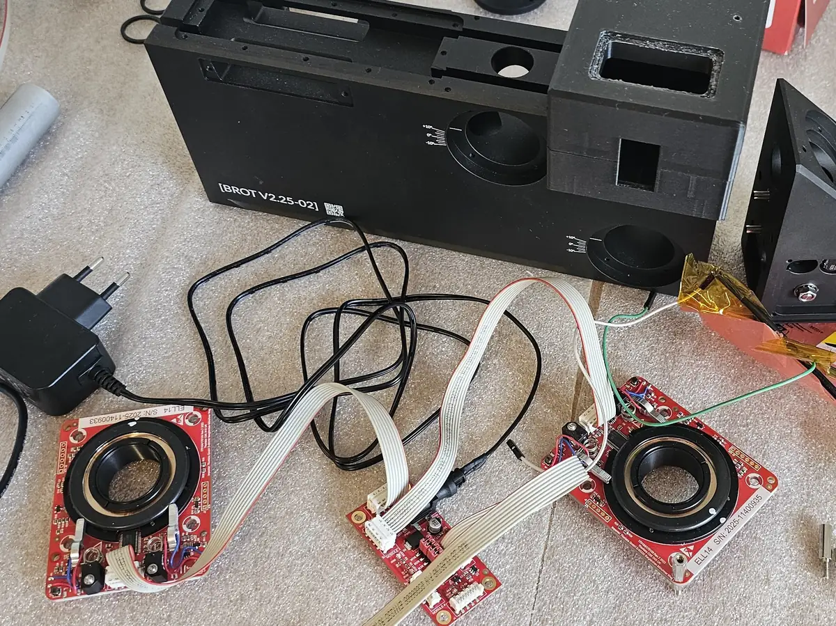
The mechanical filter wheel of the BROT can now be replaced by a motorized wheel driven remotely. Built around Thorlabs® ELL14 / ELL14K Motorized SM1 Optics Rotator modules, it sets the laser attenuation from the control software instead of by hand, without opening or touching the optical head.
- Straight path: 100 % transmission, no filter in the beam
- First stage: one position at a time — direct, OD 1 or OD 2
- Second stage: a continuously variable neutral-density wheel driven over 270°, from OD 0 to OD 1, added on top of the first stage
- Combined range: from 100 % transmission down to OD 3
- Rotators: Thorlabs® ELL14 / ELL14K Motorized SM1 Optics Rotator Kit
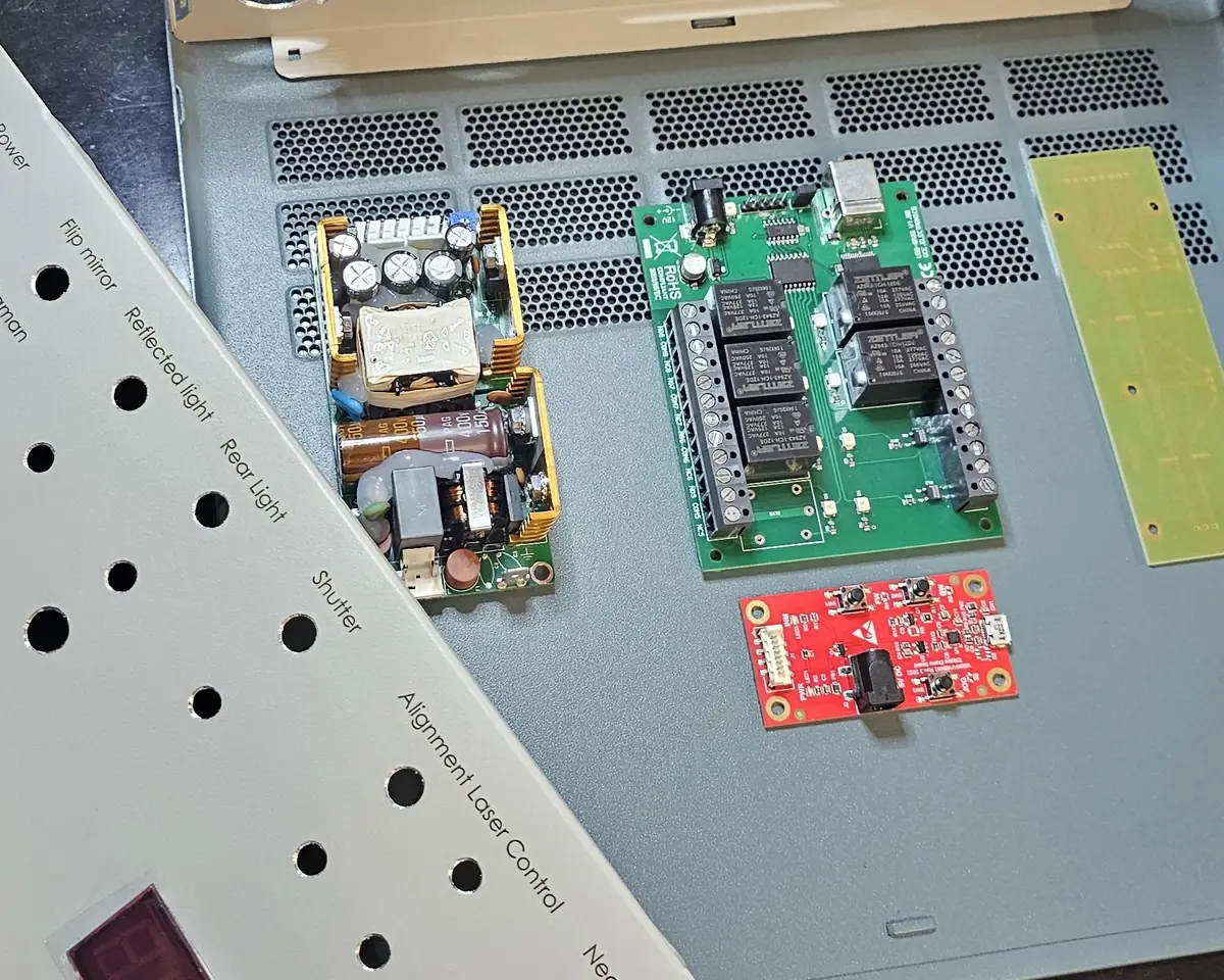
- Electronics: driver, relay board and power supply integrated inside the BROT enclosure, behind a dedicated front panel
Option under development for the BROT V2.25. No commercial reference yet.
Ask about this option →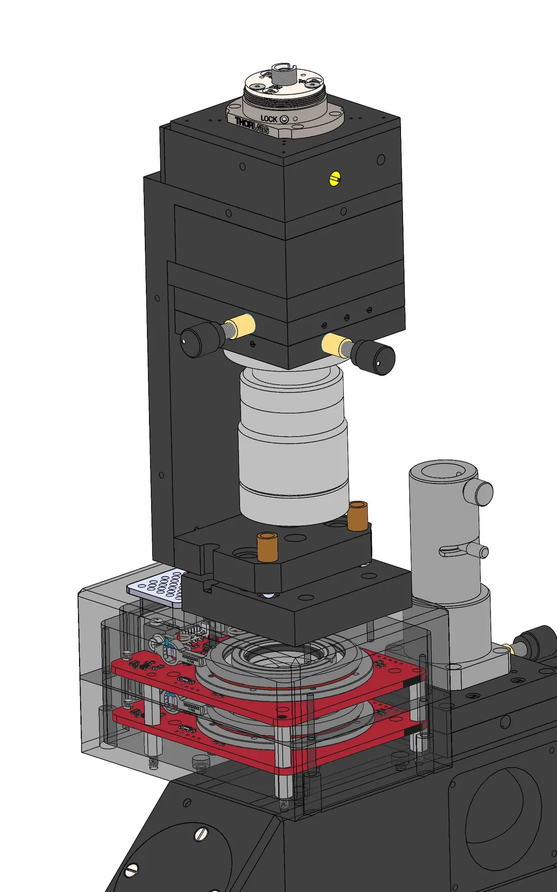
Technical data of a typical assembly
Every BROT leaves our workshop built around one bench. The optical head, the control unit and the cabling are assembled for the laser you already own, the spectrometer you already use, the room you have on the beamline or on the optical table, and the way you intend to drive it. Wavelength, objective, collection fibre, filter cut-off, cable lengths, optical axis height and mounting interface are decided with you, not taken from a shelf. That is what BETSA® has always done: the standard is where we start, not where we stop.
Optical chain
Optical head
Control unit
Power
Dry air supply
Signal output
The air supply cools the laser heat sink only. This circuit is isolated from the optical path: the air never comes into contact with the optics, and there is no risk for them. Undried air would simply condense inside the laser cooling circuit, which is why dry compressed air with a dew point below −40 °C is required.
Low-frequency cut-off
The usable low-frequency limit of the BROT is set by the filter chain in the collection path. The Raman signal passes through one 45° dichroic and three 0° long-pass edge filters, so the cut-off of the assembly is that of the least steep element, in every case the dichroic.
These figures describe the standard 532 nm filter set; for the 491 nm and 660 nm configurations, contact us. A lower cut-off can be obtained by fitting a steeper dichroic, which we configure with you according to your application. The filter value is the limit set by the optical head itself; the stray-light rejection of your spectrometer may raise it. The BROT uses edge filters and therefore collects the Stokes side only.