
Cryogenic Gas Loading System [CHCR]
Load cryogenic gases in quasi-hydrostatic conditions, on any type of diamond anvil cell. Any gas except H2, He and Ne. A safety valve secures the loading.
The equipment
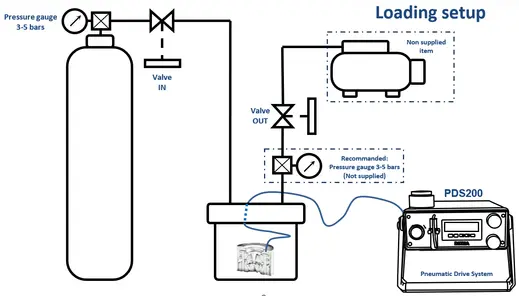
A thin stainless steel tank eases the heat transfer from the liquid nitrogen towards the gas that has to be liquefied, and a Ø65 mm laminated glass window lets you follow the operation from the outside. Safe, efficient loading calls for a dedicated installation: gas bottle, vacuum pump and safety elements.
Cryogenic loading uses liquefied gas to reach controlled experimental conditions. Compared with other loading methods it gives better thermal stability, a more accurate pressure and less disturbance from condensation or from chemical reaction of the gases.
- Compatible with all DACs of Ø35, Ø50 or Ø60 mm outside diameter — other dimensions on request.
- Lifted from the liquid nitrogen tank bottom by 3 feet, 2 eye bolts.
- External size Ø150 mm [5.9”] × 135 mm [5.3”], sealed with low-temperature O-rings.
![BETSA® Cryogenic Gas Loading System [CHCR]](/wp-content/uploads/2026/07/betsa-cryogenic-gas-loading-system-chcr1-01.webp)
Loading procedure
01Safety and equipment
Personal protective equipment suited to the handling of cryogenic material is mandatory and must comply with the safety rules of the room in use, and a dedicated workstation must be set up. The loader carries a free-exhaust safety valve: above 4.8 bar (71 psi) it opens instantly, and lets a larger flow through if the pressure keeps rising. On closing, a soft seal automatically re-establishes a perfect line of contact with the seat.
Equipment required: protective equipment for cryogenic handling, a liquid nitrogen canister, a loading gas cylinder fitted with a 3 to 5 bar pressure gauge, a primary vacuum pump — avoid oil vane pumps — a polystyrene container, a BETSA® PDS200 inflator or equivalent, piping and connections, one or two heat guns, and a membrane cell of the MDAC type or other. Two cell bases are supplied, for Ø50 and Ø60 mm.
02Preparation, installation and loading
Check that the tank is clean, degreased and dry before fitting the cell, in particular the sliding parts. Bake the membrane for one hour at 100 °C, then purge it with helium to remove any risk of blockage. Make the helium and loading gas connections, starting with the helium circuit and checking its tightness at 2 bar of membrane pressure, then fit the membrane on the loaded cell.
Place the loaded cell, slightly ajar, in the base at the bottom of the loader — with a moving piston, the piston must be at the bottom — and tighten the two clamps. Form a slight loop with the capillary so that the open micro-valve is never in direct contact with the liquefied gas. Close the cover, tighten the eight CHC screws in a star pattern and finalize the connections. Check tightness at 3 bar (44 psi) maximum. Pull a primary vacuum before opening the argon circuit, then close the gas outlet, stop the pump and set the gas pressure to 0.5 bar.
Place the loader in the cooling tank and pour liquid nitrogen up to the mark, topping the level up regularly; a Ø50 mm cell takes about one hour. Keep the outlet closed and never exceed 0.5 bar: a higher pressure shortens the loading but can prevent liquefaction from starting and risks crystallization at the end, or the loss of the load. Watch the liquid rise through the window, raise the liquefied gas above the cell, then stop both the nitrogen and the gas. Close the cell by raising the membrane pressure — it depends on the gasket indentation, the diamonds, the experimental chamber and the opening of the cell — and hold it constant within ±1 bar.
03Opening, control and measurement
Take the loader out of the tank and proceed with degassing: warming in ambient air creates an internal overpressure, so open the gas outlet valve to let the gas escape, watching for ice plugs caused by cryogenic pumping. Keep adjusting the inflator so the membrane pressure never drops. Warm the loader with a heat gun and open it once no frost remains on the thick parts, without heating the connections or the safety valve directly — the internal seals are rated from −195 °C to +75 °C.
Disconnect the gas circuit, unscrew the eight CHC screws from the cover and lift it carefully, the cell still being attached to it, then bring the cell back to room temperature very gently. Close the micro-valve once the pressure and the temperature are stable, disconnect it from the cover and reconnect it to the inflator at a pressure equivalent to the closing pressure — mind the length of the capillary, its internal volume can create an over-pressure or an under-pressure on reopening. Finally, measure the pressure to confirm that the cell closed correctly, if possible before closing the micro-valve.
Example configuration
Culet size 300 µm. Stainless steel gasket 250 µm indented to 35 µm at an inflator pressure of 40 bar, then drilled to Ø125 µm.
Cell closed at a membrane pressure of 25 bar. Pressure measured after closing: 1.7 GPa at 20 °C.